
Solder Alloy Plating
Electroplating & electroless plating · Electrolytic bath
Solder plating deposits tin-lead or lead-free tin-alloy material on terminals, busbars, lids, and machined electronic parts to provide a controlled solderable surface.
Reference page — Solder plate is not in the instant-quote configurator. Upload the part, name the finish in the notes, and an engineer quotes it with the part.
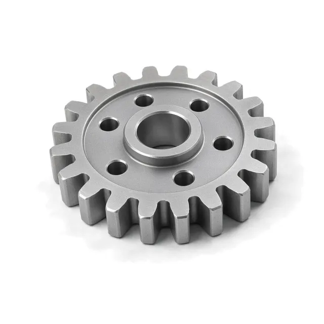
What is Solder plate?
It is relevant where a drawing requires a solder alloy rather than pure tin.
How it works
The cleaned and activated part is cathodically plated from an electrolyte containing tin and the selected alloying metal. Tin-lead processes commonly target eutectic or near-eutectic composition; lead-free alternatives include tin-copper and tin-bismuth, selected for assembly temperature and reliability. A nickel underplate can limit copper diffusion. Reflow may homogenize composition and improve wetting, while electrolytic current distribution still creates edge-to-recess thickness variation.
Why specify it
- Supplies a ready-solderable 5–25 µm surface
- Alloy can match the assembly solder process
- Reflow can verify wetting and homogenize deposit
- Useful on busbars, terminals, lids, and electronic housings
Where it falls short
- Tin-lead is restricted by RoHS except exemptions
- Lead-free alloys need higher or different reflow profiles
- Composition must be measured and controlled
- Tin-rich deposits retain whisker concerns
Solder plate at a glance
Solder plate is a middle-of-the-range finish; its best score is corrosion protection (42 of 100), at a standard cost. It adds little surface hardness.
Each score is 0–100 against every finish in this catalog. Corrosion comes from salt-spray life (ASTM B117, log scale) and hardness from the finish layer's Vickers or pencil hardness; cosmetic, lubricity and cost are FabDigit's engineering assessment. Economy on the radar is the inverse of cost.
Solder plate key numbers
Typical values from the governing specifications and shop practice; bars are this finish against the highest value among electroplating & electroless plating finishes.
- Thickness
- 5–15 µm for terminals and solderable hardware; 15–25 µm where reflow or heavier solder reserve is specified
- Hardness
- 10–30 HV — Soft alloy deposit; composition and reflow condition control hardness.
- Electrical
- Conductive
- Colours
- silver gray
- Appearance
- Matte to bright silver-gray; reflow produces a smoother fused surface.
Where Solder plate sits among all finishes
Surface hardness (Vickers, log scale) against corrosion protection (salt-spray hours, log scale) for every coating FabDigit offers, one cloud per finish group. Solder plate is highlighted; hover a dot for its name or open the full map.
Specifications for Solder plate
The documents a drawing cites to define this finish, with the Type / Class rows that apply. Each links to a page explaining the standard.
Drawing call-out
LEAD-FREE Sn-0.7Cu SOLDER PLATE, 10–15 µm, OVER 2.5 µm MIN NICKEL UNDERPLATE; REFLOW AND VERIFY SOLDERABILITY PER CUSTOMER SPECIFICATION; RoHS COMPLIANTWhich materials take Solder plate?
Verdict per material family, with the grades that behave differently. Each family links to its datasheets in the material library.
| Material family | Verdict | Notes |
|---|---|---|
| Yes | Common solderable hardware substrate after cleaning; nickel underplate is often used. | |
| Yes | Primary terminal and busbar substrate, commonly with nickel barrier. | |
| With care | Requires underplate and corrosion protection at cut edges. | |
| Limited | Requires specialized activation and multilayer underplating. | |
| Limited | Only for metal AM electrical hardware after porosity review. | |
| Limited | Requires aggressive activation; nickel underplate is usual if specified at all. | |
| Limited | Possible on some hardware after a strike. | |
| No | Fused-filament polymers are incompatible with this process. | |
| No | Incompatible. | |
| No | Polymer powder-bed prints are incompatible with this process. | |
| No | Organic polymers cannot take this inorganic metal-finishing process. | |
| No | Photopolymer prints are incompatible with this process. | |
| No | Polymer powder-bed prints are incompatible with this process. | |
| No | Titanium is not a solder-plate substrate. |
How Solder plate is applied, and what it does to the part
- 1Clean
- 2Activate
- 3Nickel underplate if required
- 4Plate controlled solder alloy
- 5Rinse
- 6Optional reflow
- 7Composition and solderability test
| Dimensions | Allow 5–25 µm solder plus underplate; molten reflow can redistribute material at edges and holes. |
|---|---|
| Build-up per side | 5–25 µm — Electrolytic deposit plus any nickel underplate; edges build faster than recesses. |
| Masking | Usually needed. Mask weld zones, contact surfaces requiring another finish, threads, and hermetic-seal lands as applicable. |
| Electrical | Conductive |
| Appearance | Matte to bright silver-gray; reflow produces a smoother fused surface. |
| Added lead time | 4–8 working days on top of the bare part |
Design rules for Solder plate
What to decide on the drawing before the part goes to the finisher.
- Name alloy composition and tolerance.Tin-lead, tin-copper, and tin-bismuth reflow differently.
- Specify lead-free status explicitly.Tin-lead is restricted unless a documented exemption applies.
- Define underplate.Nickel controls copper diffusion and intermetallic growth.
- Qualify the assembly thermal profile.Lead-free alloy liquidus and wetting differ from Sn-Pb.
Solder plate versus the alternatives
Finishes engineers weigh against Solder plate, and when each wins.
| Finish | Corrosion | Hardness | Cosmetic | Cost | Thickness | Choose it when |
|---|---|---|---|---|---|---|
Solder plate this page | 42 | 9 | 35 | $$ | 5–25 µm | — |
| 34 | 0 | 45 | $$ | 3–15 µm | when pure matte tin satisfies solderability and whisker controls | |
| 55 | 39 | 72 | $$$$ | 5–20 µm | when high-current conductivity and solderability are both required |
The radar overlays Solder plate with Tin Plating, its most common alternative — chosen when pure matte tin satisfies solderability and whisker controls. Scores in the table are 0–100 across every finish in the catalog.
Cost, lead time and compliance
Relative cost
Solder Alloy Plating is a standard-cost finish ($$): cheaper than about 67 % of the finishes FabDigit quotes.
Finishing is priced per part with a lot minimum, from FabDigit's own China-side rates. The exact figure appears on the instant quote once the part is uploaded.
Lead time and compliance
| Added lead time | 4–8 working days |
|---|---|
| RoHS | Restricted |
| Notes | Tin-lead is restricted except applicable exemptions; lead-free alloy must be explicitly named and supplier-certified. |
What Solder plate is used for
- Solderable terminals
- Busbars
- Electronic package lids
- Grounding lugs
- Machined connector parts
Solder plate — frequently asked
tin plating vs solder plating
Tin plating is nominally pure tin, commonly 3–15 µm. Solder plating intentionally includes another metal such as lead, copper, or bismuth and is commonly 5–25 µm to match an assembly process.
is tin lead plating RoHS compliant
Generally no, because lead exceeds the RoHS homogeneous-material limit unless a specific exemption applies. Use a named lead-free alloy or document the product exemption.
what lead free solder can be plated
Tin-copper and tin-bismuth are among practical plated lead-free systems, while pure matte tin is also common. The assembly temperature, whisker plan, ductility, and supplier capability determine the correct alloy.
how thick is solder plating
Solderable hardware commonly uses 5–15 µm, while 15–25 µm can provide a larger solder reserve or support reflow. Include any nickel underplate separately.
does solder plating need reflow
Not always, but reflow can homogenize alloy, reduce porosity, and demonstrate wetting. It can also redistribute a 5–25 µm deposit and expose heat-sensitive substrate issues.
Other electroplating & electroless plating finishes
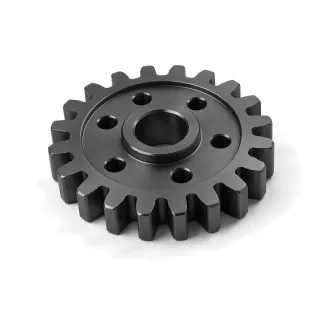 Black Nickel PlatingBlack nickel is a thin dark decorative electrodeposit, commonly applied over nickel, copper, brass, or zinc.CorrosionHardnessCost$$$
 Brass PlatingBrass plating co-deposits copper and zinc to give steel, zinc die castings, or copper alloys a yellow decorative surface.CorrosionHardnessCost$$$
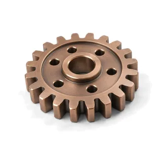 Bronze PlatingBronze plating deposits a copper-tin or related copper alloy for warm decorative color, antiquing, or selected functional bearing surfaces.CorrosionHardnessCost$$$
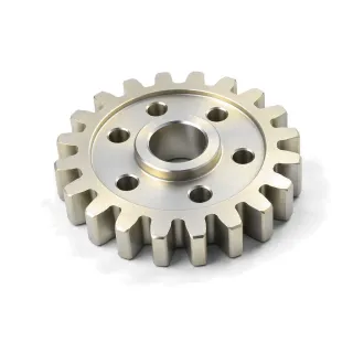 Cadmium PlatingCadmium is a sacrificial, lubricious coating retained mainly for aerospace, defense, and legacy hardware.CorrosionHardnessCost$$$$
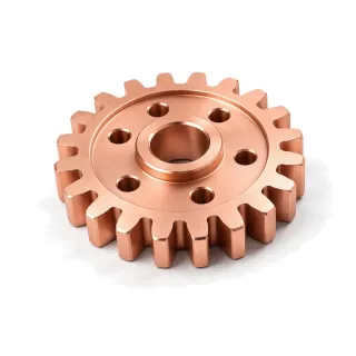 Copper PlatingCopper plating is a conductive, ductile undercoat used for leveling, adhesion, shielding, and build-up.CorrosionHardnessCost$$
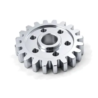 Decorative Nickel-Chrome PlatingDecorative chrome is a multilayer system: copper when needed, one or more nickel layers, and a very thin chromium topcoat.CorrosionHardnessCost$$$
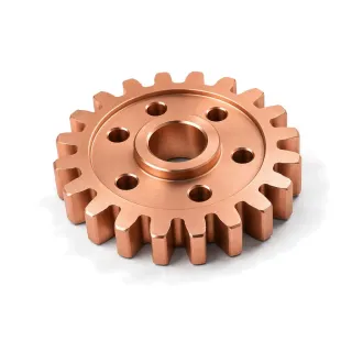 Electroless Copper PlatingElectroless copper chemically deposits a conductive seed layer on catalyzed plastics and inside printed-circuit through-holes.CorrosionHardnessCost$$$
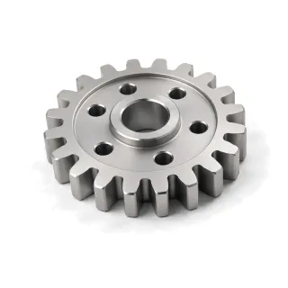 Electroless Nickel PlatingElectroless nickel is an autocatalytic nickel-phosphorus coating with nearly uniform thickness on complex geometry.CorrosionHardnessCost$$$
Compare every electroplating & electroless plating finish side by side →