FabDigit
Drones & UAV

Every gram is a watt-minute. We spend yours well.

Carbon airframes, CNC motor mounts, gimbals, ESCs, payload bays, and antenna housings for drones, eVTOL, and unmanned platforms. From a single proto frame to a 500-airframe production cell — built to your hover budget, not ours.

CNC-machined aluminum motor mount on a carbon-fiber drone arm
What makes this hard

Three engineering realities every drone program eventually meets.

Hover time is downstream of every gram and every watt on the platform. These three tradeoffs are where 80 % of drone programs leave performance on the table — and where we add the most value early.

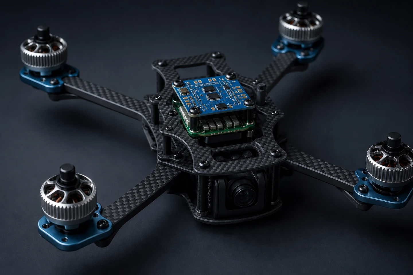
Mass and stiffness fight a zero-sum game.

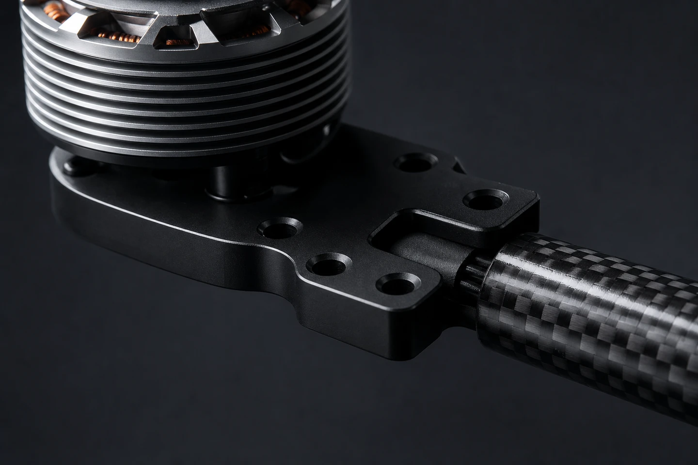
A 6 % stiffer frame buys you yaw-rate authority. The same 6 % usually costs you 12 g, which costs you 38 seconds of hover. We design the arm cross-section, layup schedule, and motor-mount geometry together — not in three siloed bids.

Vibration kills cameras, ESCs, and IMUs.

Bent motor shafts and unbalanced rotors broadcast a tone into your flight stack. We balance rotors to ISO 1940 G6.3, machine motor mounts with concentric bearing seats, and certify each frame on a shake table before it leaves the cell.

Antenna placement is structural.

A perfectly engineered carbon airframe is a Faraday cage. We design antenna cut-outs, dielectric inserts, and ground-plane breaks into the frame at layup time — not as a retrofit after first flight test.

Capability map

Six factories, one PM, one BoM for the whole airframe.

A modern UAV bill of materials pulls from carbon layup, CNC, sheet, IM, 3DP, and PCBA. You shouldn’t need six suppliers — every part below ships from a single FabDigit cell against a single drawing pack.

Capability envelope

What we typically ship — and where the airframe moat sits.

Working ranges across recent UAV programs. The coatings row carries the moat: finishes restricted on US/EU lines that our partner cells still run routinely.

Mechanical tolerance
On motor face and gimbal bores.
±0.1 → ±0.025 mm
First-article lead time
Carbon layup + cure adds to a CNC-only path.
10 – 18 days
Prototype run size
Frame proto cell.
1 – 30 frames
Production cell size
Per-week sustained airframe throughput.
100 – 500 frames / wk
Rotor balance
Custom propeller and rotor assemblies.
G2.5 – G6.3
Coatings & finishes
Anodise, plate, paint, and EMI finishes used routinely on UAV hardware. Restricted-elsewhere lines marked with a flag.
Hard anodize Type III (sealed)Chromic anodize Type IUSChemical conversion (Alodine 1200)USElectroless nickelEMI conductive coatMatte-black powder coatCataphoretic dip (e-coat)Dielectric clear-anodizeCarbon clear-coat UV-stablePTFE-impregnated anodize
A reference build

Anatomy of a production quadcopter airframe.

A composite of the X-class platforms we currently build for — 2 kg AUW, 38-minute hover, BVLOS-rated radio. Each callout is where the engineering trade-off actually lives.

Quadcopter X-frame airframe assembled on a charcoal-grey backdrop
01 · Motor + mount
02 · Carbon arm
03 · Flight ctrl
04 · ESC stack
05 · Camera bay
06 · Rotor disk
  1. 01

    1 · Brushless DC motor + CNC mount

    CNC-machined anodised motor plate, bolt-pattern matched to the stator. Bearing seat machined integral so the rotor disk stays planar to ±0.02 mm.

  2. 02

    2 · Carbon-fiber tubed arm

    UD-stacked carbon arm with 0/45 outer plies for torsion, 0/90 inner for bend. Co-bonded into a CNC aluminum collar at the body end.

  3. 03

    3 · Flight controller PCB

    8-layer FC with redundant IMU, ENIG finish, conformal-coated. Mounts on vibration-isolated standoffs so the platform-mode tone never reaches the IMU.

  4. 04

    4 · 4-in-1 ESC stack

    High-current ESC with thermally-relieved copper pours and a machined heat-spreader bonded to the top plate carbon for convective dissipation.

  5. 05

    5 · Payload bay + gimbal interface

    Monocoque carbon bay with a CNC-machined aluminum gimbal lock plate. ISO 9409-1 hand-tool quick-change pattern.

  6. 06

    6 · Rotor disk + balanced propeller

    Injection-moulded GF-PA66 propeller, balanced to ISO 1940 G6.3. Hubs come pre-loctited with the rotor adapter.

Parts we ship most

Six part archetypes that drive a UAV bill of materials.

Across the drone programs we ship, these six parts make up the majority of the spend. The spec ranges below are working envelopes — your drawing tightens them further.

Carbon airframe

Top + bottom plate, arm tubes, payload bay. Twill 2×2 cosmetic or UD-stacked structural. Autoclave-cured with ply-by-ply traceability.

Material
T300 / T700 / M40 pre-preg
Process
Autoclave layup
Tolerance
±0.15 mm cosmetic
Run size
5 – 800 pcs

Motor mount

Anodised aluminum or magnesium-alloy motor plate. Integral bearing seat machined in the same op as the bolt pattern.

Material
7075-T6 · AZ31 Mg
Process
4-axis CNC
Tolerance
±0.025 mm bore
Run size
50 – 5,000 pcs

Gimbal yoke

2- or 3-axis gimbal yokes, integral motor-stator pocket, bearing cup pre-finished. Lightweight magnesium when the weight budget demands it.

Material
6061-T6 · AZ31 Mg
Process
5-axis CNC
Tolerance
±0.02 mm
Run size
20 – 1,500 pcs

4-in-1 ESC

High-current 4-in-1 ESC board. Thermal-relief copper pours, heat-spreader bonding pad on the top plate, conformal-coated as standard.

Layers
4 – 8 layer
Copper
2 oz / 3 oz heavy Cu
Coating
Acrylic conformal
Run size
100 – 10,000 pcs

Payload bay

Monocoque carbon payload bay with CNC aluminum hard-points, optional dielectric window for forward-looking radio.

Material
Carbon + 6061-T6 inserts
Process
Layup + bonding
Tolerance
±0.15 mm
Run size
10 – 1,000 pcs

Antenna housing

Injection-moulded ASA / PC antenna housings with co-moulded dielectric inserts and EMI grounding tabs.

Material
ASA · PC / GF-PC
Process
IM + bonding
Tolerance
±0.1 mm
Run size
200 – 20,000 pcs
The decision tree

Pick a platform.
Watch the hover-budget add up.

Every drone program lives or dies on the hover budget. Pick a platform class to preset a sensible airframe, then nudge the sliders to see how mass and battery and motor-count cascade into hover time and range. The math is intentionally simple — same momentum theory we walk customers through on the second engineering call.

X-class precision surveying platform with payload + RTK + BVLOS radio. UD-stacked carbon monocoque, CNC inserts only at hard-points. 40 + min hover target.

Engineering data

Three questions every UAV program eventually asks.

Industry-typical ranges from recent engagements. Specific commitments land in your quote.

Chart · Cost vs volume

Cost-per-airframe by process and volume

Carbon autoclave wins on stiffness-to-weight at every volume. CNC + bonded carbon hybrid keeps unit cost flat from 1 to 1,000 pcs. Stamped + welded chassis wins only above 5,000.

$0$200$400$600$800$1000$12001101001k10kquantity (pcs) · log scaleHybrid ≈ carbon @ ~1,000 pcs
Autoclave carbonCNC + bonded carbonStamped + welded
Chart · Material profile

Airframe material trade-offs

Three real airframe materials. Carbon UD wins on stiffness-to-weight; AZ31 magnesium wins on mass + machinability; 7075 aluminum on cost + plating.

Stiffness / weighthigher = betterMachinability0–1Cost (inv.)lower = betterPlating ease0–1Vibration damping0–1EMI transparency0–1
Carbon UDAZ31 magnesium7075-T6
Chart · Build timeline

A 18-day first-airframe schedule

Freeze-to-flight-ready for a fresh quadcopter revision. Autoclave cure is the long pole; CNC + PCBA run in parallel.

d0d4d8d12d18DFM + layup review2dPre-preg cut + nest2dAutoclave cure 13dCNC mounts + gimbals5dPCBA build6dAutoclave cure 2 (top plate)2dTrim + bonding + assembly3dShake-table + balance2dHover bench-test2dCustomer FAI sign-off3d
Program lifecycle

How a UAV program moves from CAD to first flight.

Drone programs are notorious for compressed schedules and last-minute mass requirements. The six phases below are how we keep one moving without dropping any of them.

Phase 01

CAD intake & layup review

Drawings, STEP, and a weight budget land in our quote portal. An ME + a layup engineer review them within 24 hours, flagging arm cross-section, ply schedule, and bonding-zone decisions before quote.

Phase 02

Quote + first-frame kick-off

Quote out in 3 – 5 days. First frame in the autoclave within 5 days of PO; first flight-ready airframe shipped within 14 days.

Phase 03

First-article + vibration test

Frames ship with a CMM report, a coupon ply count, and a shake-table report at the platform-mode frequencies your flight stack cares about.

Phase 04

Pilot run + balance certification

Soft mould for prop, pilot run of 30 – 100 frames, rotor-balance certification on every assembly. Cpk numbers shipped before the production commit.

Phase 05

Production cell ramp

100 – 500 frames / wk sustained, autoclave + CNC + PCBA all inside one cell. Weekly OEE, monthly cost-walk, named cell lead.

Phase 06

Field support + revisions

Field returns route into engineering — broken arms, ESC failures, antenna VSWR drift. ECNs are graded, slotted into the next lot, no silent change orders.

Inside the cell

Where carbon becomes an airframe.

Dedicated carbon-fiber autoclave cell with two chambers: a 1.2 m proto pot for first-frame work, a 2.4 m chamber for production. Pre-preg cold-chain handled from cut nest to cure cycle, QR-tagged ply-by-ply.

Carbon-fiber pre-preg layup operation on an aluminum mandrel
In the field

A surveying UAV ramped from 8 to 42 minutes.

A composite of recent programs, anonymised to protect customer IP. Numbers are real ranges from the engagements they’re drawn from.

Inside a recent program · Series-A precision-surveying UAV startup, Europe

Cut hover-budget gap by 78 % through a single airframe revision — and finally hit the survey window.

The customer was hitting 22 minutes of hover on a target of 30 + 8 (survey window + RTH reserve). The previous airframe was a heavy machined-aluminum chassis sourced from two vendors, with a bonded-carbon top plate.

We redesigned the chassis as a UD-stacked carbon monocoque with CNC aluminum inserts only at motor mounts and payload bay. Net weight savings were 184 g — most of it pulled from the chassis ribs that the previous all-aluminum design needed.

First flight on the new airframe held 42 minutes of usable hover, 14 minutes above the survey window. The customer is now flying 3 × the survey area per battery; pilot count on their crew dropped by half.

Industry · UAV / precision surveyingGeography · Europe + ShenzhenProcess · Carbon layup + CNC + PCBAQuantity · 80 production airframes
The coatings moat

Five finishes US drone shops can no longer run.

EPA and OSHA rulings since 2018 have closed dozens of US-side plating and chromate lines. Our partner plants still run them daily. The short list below shows up most on UAV drawings.

Aerospace-spec anodize

Chromic anodize Type I

Hex-chromium anodise still required by some legacy aerospace specs on aluminum landing gear and motor mounts. Closed-loop bay; per-lot conductivity audited.

Conductive corrosion protection

Alodine 1200 (Cr⁶⁺ conversion)

Hex-chromium conversion on motor mounts and antenna ground plates where the electrical bond to the chassis must be conductive.

Wear protection on landing gear

Hard anodize Type III, sealed

Sealed Type III on aluminum landing gear, gimbal yokes, and motor faces. Black-dye option for low-IR signature; PTFE-impregnated for self-lubricating bearing seats.

Faraday cage on plastic

EMI conductive coat

Sprayed copper / nickel EMI coat on injection-moulded antenna housings and payload covers. Pairs with co-moulded grounding tabs.

Antenna ground-plane break

Dielectric clear-anodize

High-resistance clear anodise for antenna-adjacent regions where conductive treatments would detune the radio.

All-over corrosion + aesthetic

Cataphoretic dip (e-coat)

Black e-coat over chassis panels and brackets. Pinhole-free 25 µm uniform; ASTM B117 1,000 hr salt-spray; ESD-safe variants for sensitive avionics adjacency.

Frequently asked

The questions UAV teams keep asking us.

  • Yes — two autoclave cells, 1.2 m and 2.4 m chamber. Pre-preg handling is full cold-chain, ply-by-ply traceability with QR-tagged cut nest. Out-of-autoclave (oven-cure) is an option when the tooling lead time pushes back.

  • We routinely deliver G2.5 on custom rotor + propeller assemblies when the airframe demands it. Trim-balance fixturing is built into the production cell so the balance pass is not a bolt-on extra.

  • We build to the hardware requirements of both — material certs, fastener torque records, ply-count traceability, rotor balance reports. We don’t self-certify; we hand off a documentation pack your DER will recognise.

  • Yes. Co-moulded PEEK / PC dielectric inserts in carbon frames, or machined-PTFE replacement panels for retrofits. EMI conductive coating available for adjacent grounding regions.

  • 22 mm bore on the bearing seat, 8 mm bolt-pattern, hex motor face on a 1606 stator size. We build motor mounts for everything from micro-class racing drones to 25 kg surveying platforms.

  • Production from Shenzhen + Penang for commercial UAV; a US onshore cell for ITAR / DoD-adjacent programs. NDA before any CAD changes hands; site audits with 7 days notice.

Ship the platform, not the apology.

Send drawings, or send a sketch with a hover-time target. Either way you’ll have an ME reviewing within 24 hours and a real quote on a real schedule shortly after.

Drones & UAV — FabDigit | FabDigit