FabDigit
Humanoid & Cobotics

Robots that work earn their cycle time.

Joint housings, harmonic gearbox cases, encoder PCBs, end-effectors, and chassis panels for humanoid and collaborative robots. From a first-article joint to a 1,000-arm production cell — built to your torque, mass, and heat budget, not ours.

Precision-machined aluminum robotic joint housing on a dark studio surface
What makes this hard

Three engineering realities every humanoid program hits.

Robots that look elegant on stage tend to fail the same three ways in real cells. The teams that solve them ship hundreds of arms. The teams that don’t end up rebuilding their joint family at series-B.

Torque, mass, and heat live in one budget.

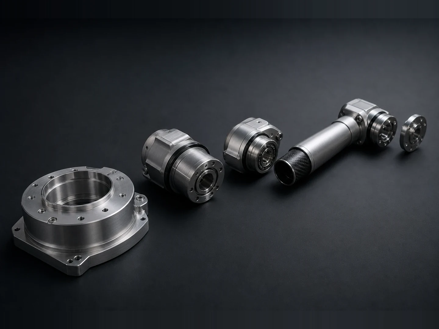
A joint is a torque source minus the mass it carries minus the heat it dumps. Sizing one in isolation makes the next one in the chain a problem. We hold the geometry tight enough that the joint your simulator picked actually fits the kinematics you shipped.

Mass at the wrist costs 6× at the hip.

Every gram added past the elbow ripples back through the kinematic chain. Pulling 40 g out of an end-effector houses turns a 2 kW shoulder joint into a 1.2 kW one. We design hardware that respects the cascade — proto in 3 days, refine in 7, freeze in 14.

For cobots the housing is the safety case.

Speed-and-separation safety lives or dies on the housing edge radius, the skin compliance, and the encoder redundancy. ISO 10218 and ISO/TS 15066 don’t care about the algorithm if the hardware lets you pinch a finger.

Capability map

Six factories, one PM, one BoM for the whole robot.

A humanoid bill of materials pulls from five processes. You shouldn’t need five suppliers — every part below ships from a single FabDigit cell against a single drawing pack.

Capability envelope

What we typically ship — and where the joint family sits.

Numbers below are the working ranges we deliver across recent humanoid and cobot programs. The coatings row carries our moat: surface treatments restricted on US/EU lines that our partner plants still run routinely.

Mechanical tolerance
On joint housing bearing bores and wrist mounting faces.
±0.05 → ±0.005 mm
IT5 on critical features
First-article lead time
CAD-frozen → first joints on a plane.
8 – 21 days
Prototype run size
Joint / wrist proto cell.
1 – 60 pcs
Production cell size
Rolling per-week throughput, sustained.
200 – 1,000 joints / wk
Bore concentricity
Adjacent bearing bores on a joint housing.
0.005 – 0.015 mm TIR
Coatings & finishes
Conductive, dielectric, wear, and aesthetic finishes used routinely on cobot and humanoid hardware. Restricted-elsewhere lines marked with a small flag.
Hard anodize Type III (sealed)Black sulfuric anodize Type IIChemical conversion (Alodine 1200)USHex-chromate touch-upUSElectroless nickel + boronPTFE-impregnated anodizePowder-coat (RAL match)Bead-blast + brushedCataphoretic dip (e-coat)Selective black-oxide on steel
A reference build

Anatomy of a 6-DOF cobot arm, decomposed.

A composite of the manipulators we currently ship — 6-DOF, ~25 kg payload, 1.4 m reach, 800 W per joint sustained. Hover any callout for the FabDigit hand-off behind that surface.

Exploded view of a 6-DOF cobot arm laid out on a charcoal-grey backdrop
01 · Base flange
02 · Shoulder joint
03 · Elbow joint
04 · Forearm tube
05 · Wrist + flange
06 · End-effector
  1. 01

    1 · Base flange — 7075-T6 CNC

    4-bolt machined base, ±0.01 mm flatness on the mating face so the kinematic zero matches your simulator. Hard anodise + Alodine touch-up.

  2. 02

    2 · Shoulder joint housing

    Wall thickness driven by torque target; bore concentricity 0.01 mm TIR. Bearing surface fluid-honed inside the cell — no separate super-finish vendor.

  3. 03

    3 · Elbow harmonic gearbox case

    Co-machined with the bearing carrier — saves three stack-ups of GD&T. We can use Nabtesco RV, HD CSG, or your in-house actuator.

  4. 04

    4 · Forearm tube

    Hybrid: machined aluminum collars at both ends, carbon-fibre wrap in the middle. Saves ~ 38 % wrist-distal mass vs all-aluminum.

  5. 05

    5 · 2-DOF wrist module

    Pitch + roll, polished steel output flange. Encoder PCB sits inside the housing — one connector exit, no external harness.

  6. 06

    6 · Quick-change end-effector

    ISO 9409-1-50-4-M6 pattern, pneumatic + electrical pass-through. Swap heads in < 8 s without retraining the kinematic offsets.

Parts we ship most

Six part archetypes that drive a humanoid bill of materials.

Across the humanoid and cobot programs we ship, these six parts make up the majority of the spend. The spec ranges below are working envelopes, not commitments — your drawing tightens them further.

Joint housing

Cylindrical or hex housing that carries the bearing + motor + gearbox. Wall thickness, bolt-pattern, and bore concentricity all hand-tuned per joint.

Material
7075-T6 · 6082-T6
Process
5-axis CNC
Tolerance
±0.005 – 0.025 mm
Run size
20 – 2,000 pcs

Harmonic gearbox case

Concentric machined case for a strain-wave gearbox. Co-machined bearing seats reduce the GD&T stack-up by a full datum chain.

Material
7075-T6 · 4140 PHT
Process
5-axis + grinding
Tolerance
±0.005 mm bore
Run size
10 – 1,000 pcs

Encoder PCB

4 – 8 layer absolute-position encoder boards. Magnetic or optical sensors, redundant where ISO/TS 15066 demands it.

Layers
4 – 8 layer
Min trace
3.5 mil / 3.5 mil
Surface
ENIG / Hard gold
Run size
50 – 5,000 pcs

End-effector

Two-jaw, three-jaw, or vacuum grippers; quick-change mounting plate. Aluminum or PA12 SLS for proto, hardened steel for production wear surfaces.

Material
AlSi10Mg · PA12 · 17-4PH
Process
CNC + SLM + SLS
Tolerance
±0.025 mm
Run size
5 – 500 pcs

Chassis panel

Torso panels, end-cap covers, and capacitive-skin housings. Aluminum sheet for structural, GF-PA66 IM for skin housings.

Material
5052 / 5754 / GF-PA66
Process
Sheet + IM
Tolerance
±0.15 mm sheet
Run size
50 – 2,000 pcs

Safety MCU board

Cat-3 / PL-d redundant safety controller. ISO 13849-1 architecture, conformal-coated for skin proximity, certified against your integrator’s acceptance test plan.

Layers
6 – 10 layer
Min trace
4 mil / 4 mil
Coating
Acrylic conformal
Run size
100 – 5,000 pcs
Scope

Where the bill of materials splits.

You design the joint. We machine the metalwork everything else bolts into — and integrate the gearbox, bearing, and actuator from your supplier list (or ours). Pick a joint to see the typical split.

Largest joint in the chain. Bore concentricity drives the rest of the bill of materials — we hold ±0.005 mm so the harmonic seats true on the first cycle.

In our shop

We machine

Parts that come out of our CNC cell or PCB house. We hold the tolerance and ship the FAI.

  • Joint housing7075-T6 · 5-axis CNC · ±0.005 mm bore
  • Harmonic-drive case4140 PHT · co-machined bearing seats
  • Output flange17-4 PH H1075 · ground OD
  • Encoder PCB8-layer · ENIG · ±25 µm trace
In our supply chain

We source + integrate

Bought-in components we order, test, and assemble into the housing. Pick a partner or send us your AVL.

  • Harmonic gear setNabtesco RV-160 · HD CSG-32 · or your spec
  • Cross-roller bearingTHK RB-15030 · IKO CRBT
  • BLDC actuator48 V · ≥ 480 Nm peak, per program
On your side

Customer-furnished

Line items we don’t touch — sized, supplied, or owned by your team. We make sure our parts mate to them, no surprises.

  • Safety brakeTypically customer-furnished
  • Wire harnessCustomer-routed; we machine the boss
  • Firmware + tuningCustomer-owned
Engineering data

Three questions every humanoid program eventually asks.

Industry-typical ranges from recent engagements. Specific commitments land in your quote — not in a marketing page.

Chart · Cost vs volume

Cost-per-joint-housing by process and volume

5-axis CNC wins on the first 200 housings — lead time, geometry agility, no tooling at risk. As volume scales, near-net hybrid casting wins on unit cost but locks the wall.

$0$100$200$300$400$5001101001kquantity (pcs) · log scaleCNC ≈ cast @ ~200 pcs
5-axis CNCVacuum cast + finishSLM AlSi10Mg + finish
Chart · Material profile

Joint housing material trade-offs

Three real housing materials. 7075 wins on stiffness-to-weight; 6082 wins on cost + plating; AlSi10Mg (SLM) wins on lattice-fill mass reduction.

Stiffness / weighthigher = betterMachinability0–1Cost (inv.)lower = betterPlating ease0–1Lattice fill3DP onlyHeat dissipationW/m·K
7075-T66082-T6SLM AlSi10Mg
Chart · Build timeline

A 21-day first-arm schedule

Freeze-to-arm-on-test-stand for a fresh 6-DOF cobot revision. Parallel where it can be, never serial when it doesn't have to be.

d0d5d10d15d21DFM review + freeze2dStock procurement2d5-axis fixtures2dJoint housing CNC6dCarbon forearm wrap5dEncoder PCBA8dAnodise + Alodine3dArm assembly + zero cal4dRun-on-stand 4 hr2dCustomer FAI sign-off2d
Program lifecycle

How a humanoid program moves from CAD to cell.

Most humanoid programs we onboard skip three of these phases on first pass. We make sure none of them get skipped silently — every phase has a deliverable you sign off on before we move to the next.

Phase 01

CAD intake & joint-family review

Drawings + STEP + simulator outputs land in our portal. An ME reviews each joint within 24 hours, flagging bore stack-ups, plating choices, and tolerance margins before quoting.

Phase 02

Quote + prototype kick-off

Quote out in 3 – 5 days. First joint on a machine within 5 days of PO; first parts in your hand within 8 – 14 days, full arm within 21.

Phase 03

First-article + run-on-stand

Joints ship with a coupon CMM, encoder zero-test, and 4-hour run-on-stand at rated torque. Reports are pushed before parts.

Phase 04

Pilot cell + SPC ramp

Soft tooling, 50 – 100 pc pilot, real Cpk on the bearing-bore concentricity and harmonic-drive case TIR before any production commit.

Phase 05

Production cell ramp

200 – 1,000 joints/wk sustained inside a single named cell. Daily SPC, weekly OEE, monthly cost-walk on the next 12 months.

Phase 06

Field support & joint revisions

Field returns route into engineering. ECNs are graded, cost-impacted, and slotted into the next lot — no silent change orders, no surprise re-validations.

Inside the cell

Where aluminum becomes a joint.

Dedicated 5-axis CNC cells for joint housing and harmonic- drive case work. Climate-controlled to ±1 °C so a 90 mm bore stays inside 0.005 mm TIR across the second pass. Coupon-tested each shift; SPC charts pushed to your QC team before the lot ships.

A 5-axis CNC machining centre cutting an aluminum robotic joint housing
In the field

A bipedal startup ramped joints in 21 days.

A composite of recent programs, anonymised to protect customer IP. Numbers are real ranges from the engagements they’re drawn from.

Inside a recent program · Series-A humanoid robotics startup, USA

Collapsed three vendors into one cell — and finally hit the wrist mass target.

The customer was 40 g over budget at the wrist on a 16 kg bipedal platform. The previous vendor stack (Mongolia / Taiwan / Suzhou) ran on different drawing revs and couldn’t agree on what the encoder PCB cut-out should look like.

We onboarded the joint family in three days, redrew the encoder cut-out into the housing during the DFM call, and shipped the first arm in 14 days. Wrist mass landed 6 g under the original target — most of the saving came from co-machining the bearing carrier into the gearbox case.

The next 200 joints shipped on a 21-day rolling cadence. The customer’s next two arm SKUs are already on our DFM queue.

Industry · Humanoid roboticsGeography · USA + ShenzhenProcess · CNC, PCBA, sheet metalQuantity · 200 joints (six SKUs)
The coatings moat

Five finishes US robotics shops can no longer run.

Environmental rulings since 2018 have closed dozens of US-side plating lines, especially the ones our customers’ joint housings need. Our domestic partners still run them daily. The short list below is what shows up most on cobot drawings.

Conductive corrosion protection

Alodine 1200 (Cr⁶⁺ chemical conversion)

Hex-chromium conversion on joint housings and base flanges where the bond to the chassis needs to be electrically conductive. Closed-loop bay, full neutralisation, audited each lot.

Joint-bore wear protection

Hard anodize Type III, sealed

Sealed Type III on aluminum harmonic-drive cases up to 75 µm. Black-dye option keeps the joint visually quiet inside a cell. Runs alongside Type II for cosmetic edges.

Surface hardness 50+ Rockwell C

Electroless nickel + boron

Selective electroless nickel-boron on end-effector wear faces and gripper jaw surfaces. Drop-in for hardened steel where the geometry doesn’t allow a steel insert.

Low-friction joint interface

PTFE-impregnated anodize

Self-lubricating anodise on joint bores that see infrequent service. Pairs with bearing-grease holdoff zones for 10× MTBF vs bare anodise.

Sheet-panel corrosion + aesthetic

Cataphoretic dip (e-coat)

Black e-coat over chassis panels and end-cap covers. Pinhole-free 25 µm uniform, ASTM B117 1,000 hr salt-spray, ESD-safe variants available.

Low-glare hardware

Selective black-oxide on steel

M3 – M10 black-oxide steel fasteners and clamp pieces. Pairs with the anodise + powder-coat finishes so visible hardware disappears inside the housing line.

Frequently asked

The questions humanoid teams keep asking us.

  • Yes — we ask for it. Joint mass is downstream of torque target, and we’d rather you spend 30 minutes on a call with our ME than eat a re-spec mid-build. Send the kinematic chain, the rated + peak torque per joint, and the platform mass. We send back the housing wall + bearing-bore + gearbox-case configuration we recommend, with the trade-offs called out.

  • We design housings, skins, and encoder redundancy against both standards. We don’t self-certify — the cell integrator owns certification. We provide the hardware documentation pack (drawings, material certs, plating traceability, run-on-stand reports) your safety auditor will actually open.

  • Yes. We run a dedicated PCBA cell for motion-control work — 4 to 12 layers, ENIG / hard-gold, X-ray on every BGA. The encoder board lives inside the joint housing and ships co-tested with the bearing assembly.

  • Joint cells in Shenzhen and Penang, a US onshore cell in Texas for ITAR / export-controlled programs. NDAs are signed before any CAD changes hands; you can audit the cell on 7 days notice.

  • Yes. Bipedal + quadruped + parallel-mechanism platforms welcome. We can also build co-machined paired joints (e.g. CRP-style shoulder + elbow pair) when the kinematics demand it.

  • We design the housings parametric to the three or four candidate gearboxes you’re still A/B testing — bolt-pattern, bore, and output-flange shape. A swap mid-program costs a re-cut, not a re-design.

Ship the arm, not the demo.

Send drawings, or send a sketch and a torque budget. Either way you’ll have an ME reviewing within 24 hours and a real quote on a real schedule shortly after.

Humanoid & Cobotics — FabDigit | FabDigit