FabDigit
Power & Grid

Switchgear ships when the creepage budget is a CAD constraint.

Switchgear housings, busbars, transformer hardware, surge arrester components, instrument transformer secondaries, and grounding hardware for utility, transmission, distribution, and industrial programs. From a custom relay enclosure to a 5,000-substation BoM — built to your voltage class and creepage envelope, not ours.

Polished laminated copper busbar with silver-plated contact ends on charcoal backdrop
What makes this hard

Three engineering realities every grid program eventually meets.

Substations and transmission hardware fail in ways production-line hardware doesn't. Dielectric stress, fault-current heating, and lifetime-corrosion compound; the parts that survive 30 years on a pole are the ones designed against all three at once.

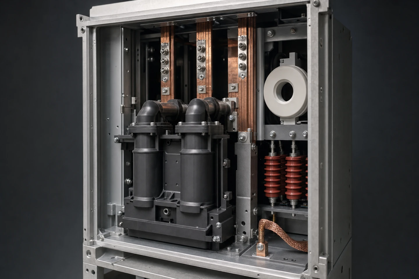
BIL and creepage are CAD constraints, not QC checks.

A 95 kV BIL bushing fails the moment you let a 1 mm burr touch a corona path. We build to IEC 60664-1 / 60815 creepage envelopes from CAD onwards — surface roughness, fillet radius, electrode polish are designed in, not buffed in.

Pollution-class is the lifetime driver, not BIL.

A 95 kV bushing that passes BIL on day one fails creep-current on year three in a coastal site. Hydrophobic shed geometry, silicone composite construction, and surface-finish chemistry decide where the part actually retires.

Field stress concentrates where the geometry ends.

Sharp edges, gas voids, and triple-points concentrate field until they ignite. We design end-fittings, grading rings, and shed terminations against the field plot — not against the mechanical-only assembly drawing.

Capability map

Six processes, one PM, one substation BoM.

A switchgear, transformer-accessory, or surge-arrester BoM pulls from copper machining, plating, sheet, casting, IM, and high-creepage PCBA. You shouldn't need six suppliers — every part below ships from a single FabDigit cell.

Capability envelope

What we typically ship — and where the grid moat sits.

Working ranges across recent switchgear, transformer-accessory, and surge-arrester programs. Coatings row carries our moat: plating chemistries restricted on US/EU lines that our partner cells still run.

Mechanical tolerance
On bus joints, flanges, and electrode geometry.
±0.05 → ±0.025 mm
Electrode surface finish
Ra on UHV grading-ring and shield-electrode geometry.
Ra 0.4 – 1.6 µm
Voltage class served
AC peak class on shipping parts.
0.4 – 800 kV AC · ±1100 kV DC
Lifetime in service
Design-life on shipping hardware.
25 – 40 yr design-life
Lot size
From a custom enclosure to a substation BoM.
1 – 5,000 ship-sets
Coatings & finishes
Platings and surface treatments used routinely on grid hardware. Restricted-elsewhere lines marked with a flag.
Silver plate, Ag 5 – 25 µm (contact)Hard-Cr, > 25 µm (wear)USHot-dip-galvanize, Zn 70 – 110 µmZinc-nickel, Zn-Ni 12 – 16 % NiTin plate (RoHS-clean), Sn 5 – 8 µmElectroless nickel, Ni-P 25 µmEpoxy powder, hydrophobic + UV-stableCycloaliphatic epoxy castingSilicone HCR composite shedCr⁶⁺ passivationEU
A reference build

Anatomy of an MV switchgear bay, decomposed.

A composite of recent distribution-switchgear programs (12 – 24 kV class). Each callout is where the engineering trade-off lives, and where the moat sits.

Open MV switchgear cabinet with copper busbars, vacuum interrupters, surge arresters
01 · Cu busbar
02 · Vacuum CB
03 · CT donut
04 · Surge arrester
05 · Ground stud
06 · Al cabinet
  1. 01

    1 · Laminated copper busbar

    ETP-copper laminated bus, silver-plated tap points (Ag 8 – 12 µm). ±0.025 mm flatness on the joint face. Belleville-stacked at every tap; lot-tracked torque on the M12 bolt.

  2. 02

    2 · Vacuum-interrupter chamber

    Cycloaliphatic-epoxy enclosure; vacuum-bottle interface machined to ±0.02 mm. Silver-plated contact-finger cluster, oxide-controlled atmosphere assembly.

  3. 03

    3 · Cast-resin CT secondary

    Cycloaliphatic-epoxy cast CT secondary, polished electrode geometry inside, IEC 61869 class 0.5S accuracy. Bonded-in temperature-stable winding form.

  4. 04

    4 · MV surge arrester column

    Silicone HCR composite-shed surge arrester, MOV-disk stack with electrode-end machined to Ra < 0.8 µm. End-fitting field plot verified before mould-flash.

  5. 05

    5 · Cu grounding stud + braid

    Tinned-Cu grounding stud, copper braid bonded to a substation earth-mat. PA pull-test traceability and 25 kA / 1 s short-time rating documented per lot.

  6. 06

    6 · Bead-blast aluminum cabinet

    Aluminum switchgear cabinet, bead-blast finish then epoxy powder-coat. Door-bolt creepage path verified before powder.

Parts we ship most

Six part archetypes that drive a substation BoM.

Six parts make up the majority of the spend on a typical distribution or transmission program. Spec ranges below are working envelopes — your drawing tightens them.

Copper busbar

Laminated ETP / OFHC copper bus, silver- or tin-plated tap zones. Machined chamfered M12 / M16 bolt-holes. Belleville-stacked joints.

Material
ETP-Cu · OFHC-Cu
Process
CNC + plate
Tolerance
±0.025 mm
Run size
10 – 5,000 pcs

Switchgear housing

Aluminum or galvanized-steel switchgear cabinet with door-bolt creepage verified. Epoxy powder-coat for tropical-class.

Material
Al · galv-steel
Process
Sheet + powder-coat
Tolerance
±0.5 mm
Run size
1 – 5,000 pcs

Transformer flange

CNC-machined aluminum or stainless flange for transformer bushings. ±0.025 mm flatness on the seal face.

Material
Al 6061-T6 · 316L
Process
5-axis CNC
Tolerance
±0.025 mm
Run size
1 – 1,000 pcs

Surge arrester column

Silicone HCR composite-shed surge arrester housing with MOV-disk stack, electrode-end machined Ra < 0.8 µm.

Material
Silicone HCR + Al
Process
IM + CNC
Tolerance
±0.1 mm
Run size
10 – 5,000 pcs

HV connector

Silver-plated Cu finger-cluster, epoxy-resin housing, weather-sealed. Cable-termination kit included.

Material
Cu + epoxy + SS
Process
CNC + plate + IM
Tolerance
±0.05 mm
Run size
50 – 5,000 pcs

Grounding hardware

Tinned-Cu grounding stud + copper braid + galvanized-steel earth-mat connector. Pull-test and short-time rating logged.

Material
Cu + galv-steel
Process
CNC + plate
Tolerance
±0.1 mm
Run size
100 – 10,000 pcs
The decision tree

Voltage class × material × coating.
The matrix substations actually ship against.

Click a voltage class, then click any cell in the matrix below. Each cell tells you whether that material × coating combination survives that voltage class — and what FabDigit builds at the intersection. The cells marked FAIL are there to tell you the substitution we'd recommend.

Material × coating · MV — Medium voltage
PASSMARGINFAILN–A
BareNo plating
Tin plateSn 5 – 8 µm
Silver plateAg 5 – 25 µm
Electroless NiNi-P 25 µm
Hot-dip galv.Zn 70 – 110 µm
Zinc-nickelZn-Ni 12 – 16 % Ni
Epoxy powderHydrophobic, UV-stable
ETP / OFHC copperC11000 · C10100
Aluminum1350 · 6061-T6 · 6082-T6
BrassCW614N · C36000
316L stainlessCrNiMo 17-12-2
Carbon steelS355 · 1018
Silicone elastomerHCR / LSR
Epoxy-glassCycloaliphatic / hydrophobic
MV — Medium voltage · ETP / OFHC copper · Silver platePASS

Silver-plated Cu finger-clusters — the moat of MV switchgear lifetime.

Engineering data

Three questions utility teams eventually ask.

Industry-typical ranges from recent engagements. Specific commitments land in your quote.

Chart · Cost vs volume

Cost-per-busbar by process and volume

Conventional copper bar is bought + cut + plated; CNC-cut + silver-plated copper wins on tap-point precision and durability. SLM Cu opens up for special shapes only past 50 pcs.

$0$50$100$150$200$250$300$350$4001101001kquantity (pcs) · log scaleCNC + Ag-plate plateau
CNC ETP-Cu + Ag-plateShear + tin-plateSLM OFHC-Cu
Chart · Material profile

Insulator material trade-offs

Three candidate insulator material families for MV / HV outdoor. Silicone composite wins on hydrophobic-transfer; epoxy wins on machinability + casting yield; porcelain wins on cost-at-scale but loses the field.

Dielectric strengthhigher = betterHydrophobic transfer0–1Impact resistancehigher = betterUV / weather stability0–1Cost (inv.)lower = betterField uniformity0–1
Silicone HCR compositeCycloaliphatic epoxyPorcelain
Chart · Build timeline

A 25-week first-article schedule

Contract-to-type-test for a 145 kV switchgear bay. Cast-resin epoxy + silver-plate parallelised; type-test campaign starts before production ramp.

d0d28d56d84d112d140d175CAD intake + field-plot14dStock procurement (Cu, Al)21d5-axis CNC fixtures + programs14dCycloaliphatic-epoxy tooling28dFirst-article CNC + Ag-plate21dFirst-article cast-resin run21dCMM + dielectric coupon14dType-test campaign (HV lab)28dProduction ramp + first ship-set35dShip-set #1 sign-off21d
Program lifecycle

How a substation BoM moves from CAD to substation type-test.

Grid programs are 18 – 36 month programs whose entire cost gate is the type-test at the high-voltage laboratory. The six phases below are how we keep the design-revision loop short and the type-test campaign clean.

Phase 01

CAD intake & field-plot review

Drawings + STEP + voltage envelope land in our portal. A high-voltage engineer reviews them within 72 hours, flagging field-concentration risks and surface-finish callouts before quote.

Phase 02

Quote + first-article parts

Quote out in 5 – 10 days. First-article parts on a 5-axis fixture within 15 days; first-article CT/PT cast and de-moulded within 25 days. CMM report ships with the parts.

Phase 03

Type-test coupon ship + CMM

CMM, surface-roughness report, BIL-coupon, lightning-impulse coupon — all packaged with the parts. We don't self-certify; we ship evidence the HV laboratory will recognise.

Phase 04

Type-test campaign support

On-site or remote support during BIL, lightning-impulse, and temperature-rise type-test at the HV laboratory. ECNs flow through engineering, not through silent change-orders on the next lot.

Phase 05

Production ramp + traceability

Heat-lot traceability per part, plating-bath audit per lot, cast-resin batch-cure documentation. Each ship-set ships with its DPL pack.

Phase 06

Substation-scale build + spares

500 – 5,000 ship-sets / year for transmission programs, with held-inventory spares per ship-set. Long-lead lots committed 24 months forward.

Inside the cell

Where aluminum becomes a transformer-bushing flange.

Dedicated grid-hardware 5-axis CNC cell for transformer flanges, bushing seats, and bus-tap geometry. Climate-controlled to ±0.5 °C, with a coupon CMM in-line so the seal-face flatness never drifts past ±0.025 mm on long parts.

A 5-axis CNC machining centre cutting a transformer-bushing flange
In the field

A 145 kV GIS program shipped 132 bays in 18 months.

A composite of recent programs, anonymised to protect customer IP. Numbers are real ranges from the engagements they're drawn from.

Inside a recent program · European TSO sub-transmission renewal, 12 substations

Cut type-test failure-mode count by 80 % by co-designing the field plot before CAD freeze.

The customer was renewing twelve 145 kV sub-transmission substations on a regulatory deadline. Their prior partner had failed BIL on the first type-test and lost six months to redesign; the schedule wouldn't move.

We embedded a high-voltage engineer into the early CAD phase and re-machined the bushing-flange geometry against the field plot — chamfer radius, electrode polish, and grading-ring transition all moved before the first part was cast. The cast-resin CT secondaries ran on our cycloaliphatic-epoxy line; the silver-plated finger clusters ran in parallel on the contact-plating cell.

Type-test passed on the first campaign with zero non-conformances. The 132-bay build ramped from prototype to ship-set #1 in 5 months; all 132 bays delivered 18 months from contract.

Industry · 145 kV GIS substation renewalGeography · Europe + ShenzhenProcess · CNC + cast-resin + silver-plateQuantity · 132 bays + spares
The coatings moat

Six surface treatments US shops can no longer keep running.

EPA / OSHA rulings since 2015 have closed dozens of US-side plating bays. Our partner plants still run them daily. The list below shows up most on substation drawings.

Wear surface · disconnect rod

Hard-chromium plate

Hex-Cr plate > 25 µm on disconnect-switch shafts and tap-changer rods. Closed-loop bay, full neutralisation, per-lot audit.

Contact moat · Ag 5 – 25 µm

Cyanide silver plating

Cyanide-bath silver for HV finger-cluster contacts. XRF per part for thickness uniformity, closed-loop water recovery.

Substation steelwork

Hot-dip galvanize, 100 µm Zn

Heavy-zinc galv for lattice towers, equipment-base steelwork, cable-tray. Per-lot zinc-bath sampling, adhesion coupons documented.

HV fastener finish

Zinc-nickel, 12 – 16 % Ni

Zn-Ni for HV hardware bolts; replaces Cd / Cr⁶⁺ chromate. Cr⁶⁺-free passivation step audited per lot.

MV / HV CT/PT secondaries

Cycloaliphatic epoxy casting

Hydrophobic outdoor cast-resin for instrument-transformer secondaries. Per-batch cure-monitor, dielectric tan-δ in-line.

Outdoor insulator moat

Silicone HCR composite shed

Silicone HCR composite-shed bonded over an epoxy-glass core. The default HV outdoor insulator at heavy-pollution sites.

Frequently asked

The questions utility teams keep asking us.

  • Yes — every BoM ships with a type-test-evidence pack: CMM, surface-roughness, BIL-coupon, lightning-impulse coupon, and for cast-resin parts the per-batch cure record. We design backwards from the laboratory test the part will face.

  • Yes — cycloaliphatic-epoxy cast resin for CT / PT secondaries and MV spacer bushings is one of our core processes. Hydrophobic over-coat available for heavy-pollution sites. Per-batch dielectric tan-δ measurement is in-line.

  • Yes — for programs over $250 k we embed an HV engineer at the CAD stage. We can run our own 2-D / axisymmetric field-plot solvers, or work to a plot you provide.

  • Yes — hot-dip-galv on carbon-steel substation steelwork (cabinet frames, lattice support, equipment-base steel) is in-line at our partner cell. Zinc thickness 70 – 110 µm per ASTM A123 / ISO 1461. Adhesion and salt-spray data ship with each lot.

  • Silver plating on Cu finger-clusters and disconnect contacts is our partner-cell moat. Bath chemistry audited per lot, X-ray fluorescence (XRF) on thickness, closed-loop water recovery for the cyanide bath. We can plate 5 – 25 µm Ag with ±0.2 µm uniformity.

  • Yes — distribution-class hardware is routinely shipped to GB/T, IS, and ANSI / NEMA standards alongside IEC. Approval-test coupons differ per standard; we package per the destination utility's acceptance protocol.

Ship the bay, not the BIL apology.

Send drawings, or send a voltage envelope and a creepage budget. Either way you'll have an HV engineer reviewing within 72 hours and a real quote on a real schedule shortly after.

Power & Grid — FabDigit | FabDigit