
A-sample to SOP collapses every assumption.
The drive unit that hit 8000 rpm on the bench at A-sample needs a 500,000-cycle stator winding by SOP. We design the housing + the PCB + the connector around the assumption set you’ll actually ship.
Inverter housings, motor stators, battery pack hardware, drive-unit casings, and high-voltage PCBs for electric vehicle platforms. From A-sample drive unit to a 50,000-unit production cell — built to your three-power architecture, not ours.
EV programs are a three-power problem — drive (motor + inverter), storage (pack + BMS), and charging (OBC + converters). The teams that win solve them together; the teams that don’t end up renegotiating their BoM 18 months after A-sample.
The drive unit that hit 8000 rpm on the bench at A-sample needs a 500,000-cycle stator winding by SOP. We design the housing + the PCB + the connector around the assumption set you’ll actually ship.
Modern e-axles run die-cast aluminum housings that ARE the coolant jacket. CNC + cast hybrid lets you proto with the production thermal profile instead of finding it 12 months in.
800 V is not 12 V × 67. Creepage, clearance, EMI gaskets, and the plating on the busbar contacts all change. We build to LV 215-2 + ISO 6469 + IEC 62133 ahead of formal qualification.
A modern EV drive unit pulls from die-cast, CNC, sheet, IM, PCBA, and specialist plating. You shouldn’t need six suppliers — every part below ships from a single FabDigit cell against a single drawing pack.
Aluminum HPDC blanks finish-machined to ±0.025 mm flatness on the sealing flange. Coolant-port back-bores and bearing-carrier seats run in the same op.
Learn morePack trays · coversPack trays in 5052 / 5754 aluminum, stamped or formed steel covers, pre-finished and welded. Powder-coat, anodise, cataphoretic dip in the same line.
Learn moreHV connectors · coversHigh-voltage connector bodies in GF-PA66 / PPS, V-0 PC covers, co-moulded EMI inserts. Hardened steel tooling rated for 1 M-shot production runs.
Learn moreCooling jackets · jigs · A-samplesSLM AlSi10Mg for first-article coolant jackets when HPDC tooling is 12 weeks out. PA12 (SLS) for assembly fixtures and ESC strain reliefs.
Learn moreInverter · BMS · OBC4 – 12 layer high-voltage power boards with 4-oz copper pours, heavy bus-tabs, conformal coat as standard. ENIG / hard-gold on busbar contacts.
Learn moreDrive integration · qualificationEmbedded engineering on stator winding selection, inverter thermal modelling, and LV 215-2 / ISO 6469 hardware compliance. Co-locate for qualification.
Learn moreWorking ranges across recent EV programs. Coatings row carries the moat: plating and conversion lines restricted on US/EU sites that our partner plants still run.
Composite of recent passenger-EV drive units. 220 kW peak, 400 V or 800 V bus, single-speed reducer. Hover any callout to see the hand-off.
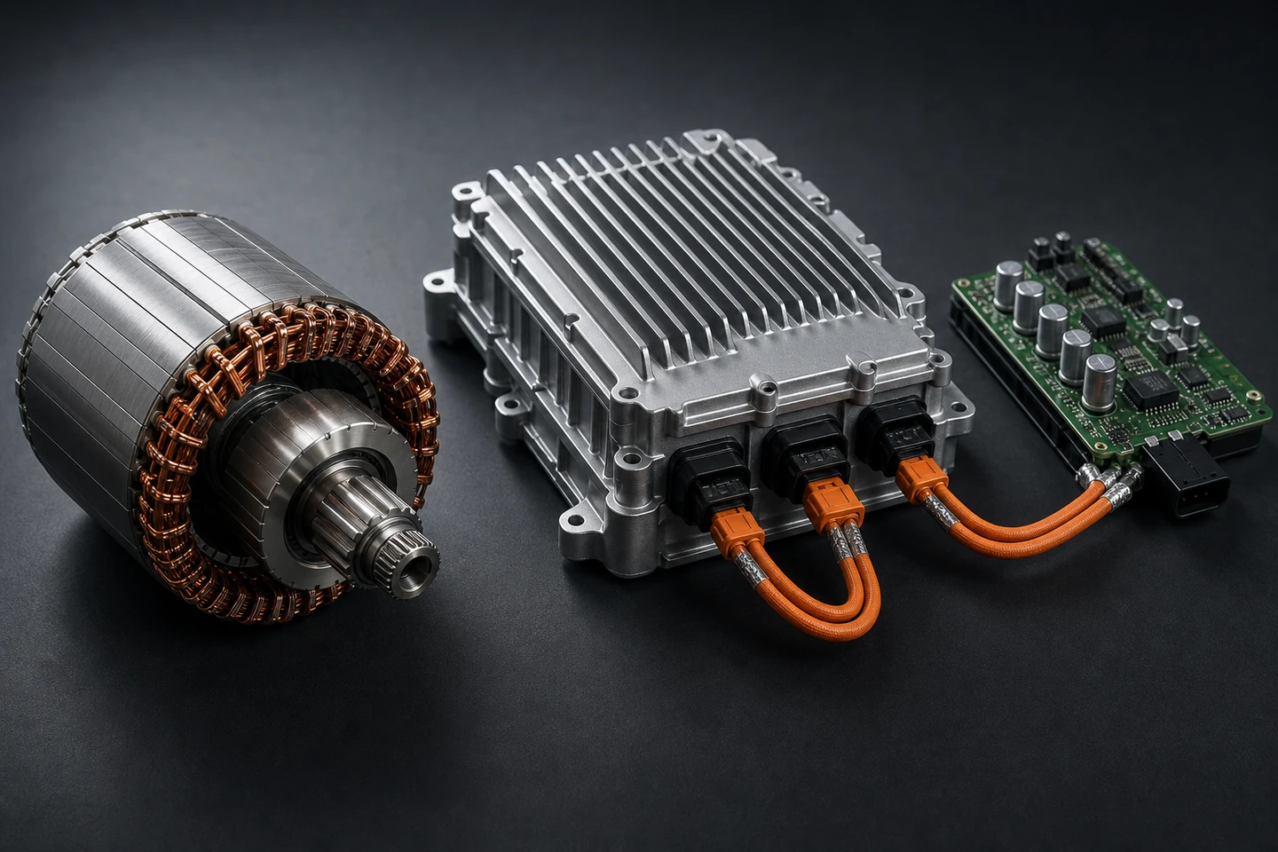
Laminated steel stator with copper hairpin windings. We build the stator carrier + bearing housing in 7075-T6, machined-to-cast tolerance.
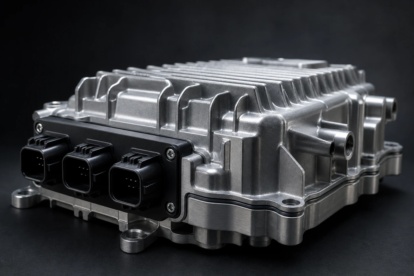
HPDC AlSi10Mg housing with integrated coolant jacket. CNC-finished sealing flange + bearing seats; flatness ±0.025 mm; helium-trace leak-tested before shipment.
IM-moulded GF-PA66 connector bodies with co-moulded EMI gaskets and silver-plated busbar lug interfaces.
6-layer PCB with 4-oz copper pours, heavy-bus tabs, and selective parylene over the HV traces. ENIG on the busbar contact pads.
Integrated into the cast housing as a labyrinth jacket. Coolant flow validated against the inverter thermal map at qualification.
Co-machined with the inverter sealing flange. Bore concentricity 0.01 mm TIR; sealed crossed-roller bearing pre-fit at the cell.
These six parts make up the majority of the spend on a typical EV drive unit. Spec ranges below are working envelopes — your drawing tightens them.
HPDC AlSi10Mg housing, CNC-finished sealing flange, integrated coolant jacket. Helium-trace leak-tested.
Machined aluminum stator-housing carrier with co-machined bearing seat. Drop-in for hairpin or distributed-winding stators.
Stamped + welded aluminum pack tray with integrated cold-plate channels. Pre-finished with cataphoretic dip and EPDM seal groove.
High-voltage 6 – 12 layer power-stage PCB. 4-oz copper pours, heavy-bus tabs, selective parylene, hard-gold busbar contacts.
Reducer-side housing co-machined with the inverter housing. Integrated mounting bosses, gasket grooves, breather seats.
IM-moulded GF-PA66 / PPS connector bodies with co-moulded EMI gaskets and silver-plated busbar interfaces.
Every cell below is a real combination FabDigit ships. Click any intersection to see the exact parts that move from vehicle class to vehicle class — and which stay fixed. The tabs filter the matrix by vehicle. The big card on the right reveals the hand-off for the selected cell.
Bus: 400 / 800 V · Power: 120 – 350 kW
B-, C-, and D-segment passenger vehicles. Highest unit volumes, tightest cost-walk, longest qualification chain — A-sample to PPAP to SOP in 24 – 36 months.
Industry-typical ranges from recent engagements. Specific commitments land in your quote.
At A-sample, SLM AlSi10Mg wins because the HPDC tool cost is irrelevant. By B-sample, soft HPDC takes over. By SOP, hard HPDC is the only game in town.
Three candidate materials. AlSi10Mg is the standard; AlSi9Cu3 is cheaper at the cost of finish; Mg AZ91 wins on mass for 2-wheeled platforms.
Freeze-to-A-sample-on-the-dyno for a fresh 220 kW drive-unit revision. SLM proto housings run in parallel with soft-tool HPDC.
Three years from CAD to SOP is the modern OEM cadence. The six phases below are how we keep one moving without dropping the qualification chain — A-sample to PPAP to SOP, with no silent overruns.
Drawings, STEP, stator winding spec, inverter topology land in our portal. An ME + a power engineer review them within 48 hours, flagging cast-feasibility, coolant routing, and PCB stack-up decisions ahead of quote.
Soft tooling for HPDC, SLM proto inverter jackets, first drive unit on the bench within 28 – 56 days of PO. Dyno test report ships with the parts.
Hardened tooling cut, 30 – 100 pc B-sample run, full PPAP package compiled: CMM, FMEA, control plan, capability study, helium-trace leak data, dyno runs.
Field-rep C-sample fleet, real-condition validation, final ECN cycle. Drawing pack freezes at the end of this phase.
1,000 – 3,000 drive units / wk inside a single cell, daily SPC, monthly cost-walk, named cell lead. Pricing curve committed on a 24-month rolling basis.
Field returns route into engineering. Cost-impacted, scheduled, no silent change orders. Production cell uses last-in-first-out BoM so the field never gets two rev levels at once.
A dedicated HPDC cell for inverter and drive-unit housings. 900-tonne and 1,200-tonne machines, in-line vacuum degassing, and a robot tending hand-off straight to the 5-axis CNC for finish-machining. Helium leak-test station inside the cell.
A composite of recent programs, anonymised to protect customer IP. Numbers are real ranges from the engagements they’re drawn from.
The customer had a 220 kW drive unit on a 38-week A-sample-to-PPAP plan with three separate suppliers (HPDC, CNC finish, PCBA). HPDC tooling lead time was the long pole at 14 weeks.
We started with an SLM AlSi10Mg first-article inverter housing — qualification-grade thermal profile in two weeks, not fourteen. The soft HPDC tool was cut in parallel; the moment the first SLM jacket passed the helium trace, we kicked off the hard tool cycle.
A-sample landed in week 12 instead of week 26. PPAP package complete in week 16. The customer hit SOP eight months ahead of original plan; the next two drive-unit variants are already on our DFM queue.
Environmental rulings since 2018 have closed dozens of US-side conversion and plating lines. Our partner plants still run them daily. The short list below is what shows up most on EV drive-unit drawings.
Hex-chromium conversion on aluminum drive-unit housings and motor mounts where the bond to chassis ground must remain conductive.
Black e-coat over pack trays, brake hardware, and chassis brackets. Pinhole-free 25 µm uniform; ASTM B117 salt-spray 1,000 hr.
Silver-on-copper selective plating on busbar lugs and HV connector pins. Spec to 4 µm uniform; closed-loop process.
Tin plating on HV connector busbar tabs for repeatable insertion force and contact resistance.
Sealed Type III on stator-carrier bearing bores and motor end-caps. PTFE-impregnated options for self-lubricating service.
In-house powder lines that can match RAL or OEM colour books, low-VOC formulations, rated for IEC 60068-2 salt-spray 500 hr.
We build to PPAP Level 3 + 4 routinely; IATF 16949 certification is held by the partner plants we deploy through. Drawing pack, FAI, PFMEA, control plan, capability study, gauge-R&R — all standard deliverables for our drive-unit programs.
Yes. HPDC blanks are loaded directly into the 5-axis CNC cells without travel through a third-party finisher. Same drawing pack, same QC team, same cost-walk.
For programs over 200 A-sample units, we run a parallel SLM AlSi10Mg first-article cell while the hard tool is being cut. The SLM jackets are qualification-grade thermal-profile parts in 2 weeks instead of 12 – 14.
Yes. Silver-plated busbar lugs, tin-plated contacts, selective gold on PCB interfaces. Plating thickness audited per lot.
Drive-unit cells in Shenzhen, Suzhou, and a US Tier-1-partner cell in Michigan for export-controlled programs. NDA and site audit available with 14 days notice.
For hairpin stators, yes — we build the carrier + bearing housing and partner on the actual winding cell. For wound stators, we handle the carriers and integrate at final assembly.
Services this industry uses most
Adjacent industries we serve
Send drawings, or send a stator winding spec + bus voltage. Either way you’ll have an ME reviewing within 48 hours and a real quote on a real schedule shortly after.