
Support Removal
3D-print & moulding post-processing · Mechanical
Support removal separates sacrificial print structures and cleans their attachment scars.
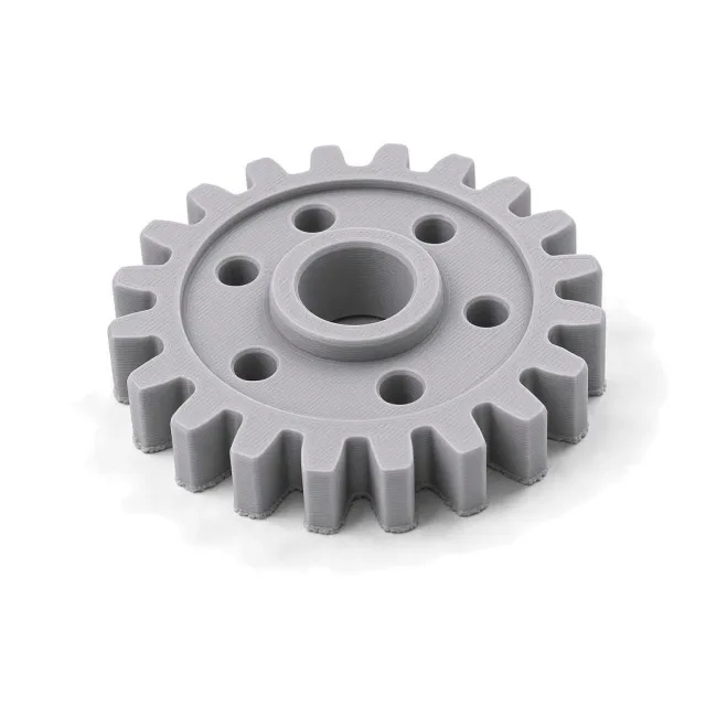
What is Support removal?
It is mandatory for supported FDM, SLA, PolyJet, and metal powder-bed parts but is an operation rather than a complete cosmetic finish.
How it works
Supports are clipped, broken, dissolved, water-jetted, machined, or cut by wire EDM according to print process and material. Contact points are then filed, sanded, or blended. Supported zones can remain much rougher than free surfaces, commonly around Ra 3.2–25 µm (125–1000 µin) before further finishing. Dimensional loss is local but can be severe if supports are fused or placed on thin walls.
Why specify it
- Makes supported geometry usable
- Removes sharp support stubs
- Exposes channels and interfaces
- Prepares scars for later sanding or blasting
Where it falls short
- Does not guarantee a uniform finish
- Can gouge surfaces and break thin features
- Internal supports may be inaccessible
- Metal removal can release residual stress
Support removal at a glance
Support removal is a middle-of-the-range finish; its best score is cosmetic quality (15 of 100), at a standard cost. It adds little corrosion protection or lubricity. Surface hardness is not rated: the finish leaves the part's own surface.
Each score is 0–100 against every finish in this catalog. Corrosion comes from salt-spray life (ASTM B117, log scale) and hardness from the finish layer's Vickers or pencil hardness; cosmetic, lubricity and cost are FabDigit's engineering assessment. Economy on the radar is the inverse of cost.
Support removal key numbers
Typical values from the governing specifications and shop practice; bars are this finish against the highest value among 3d-print & moulding post-processing finishes.
- Thickness
- No coating; cleaned support zones commonly remain Ra 3.2–25 µm (125–1000 µin) before further finishing.
- Electrical
- Unchanged
- Appearance
- Support-free part with local witness marks or blended scars.
Specifications for Support removal
The documents a drawing cites to define this finish, with the Type / Class rows that apply. Each links to a page explaining the standard.
Drawing call-out
REMOVE ALL BUILD SUPPORTS AND LOOSE MATERIAL; BLEND SUPPORT WITNESS MARKS TO Ra 6.3 µm MAX; DO NOT REDUCE WALLS BELOW DRAWING MINIMUMWhich materials take Support removal?
Verdict per material family, with the grades that behave differently. Each family links to its datasheets in the material library.
| Material family | Verdict | Notes |
|---|---|---|
| Yes | DMLS/SLM aluminum supports are cut and blended after build. | |
| Yes | Cutting, machining, and stress-relief planning are required. | |
| Yes | Breakaway or soluble supports are common. | |
| Yes | Water-jet or soluble support removal is typical. | |
| Yes | FDM, SLA, and material-jet supports are removed by breakaway, dissolve, or cut. | |
| Yes | Clip before final cure where the validated workflow requires it. | |
| Yes | DMLS/SLM stainless supports are cut and blended after build. | |
| Yes | DMLS/SLM steel supports are cut and blended after build. | |
| Yes | Standard DMLS/SLM titanium support removal with contamination control. | |
| With care | Soft copper AM supports smear; use sharp tools and light blending. | |
| Limited | Brass AM is uncommon; treat as a soft-metal support-removal trial. | |
| Limited | Rare AM alloy; fire-safe support removal required if used. | |
| Limited | Powder-bed nylon has no discrete supports; this is powder cleanup. | |
| Limited | Powder-bed nylon has no discrete supports; this is cake and powder cleanup. | |
| No | Zinc is not a typical supported AM process in this catalog. |
How Support removal is applied, and what it does to the part
- 1Identify support interfaces
- 2Cut or dissolve supports
- 3Remove stubs
- 4Blend only specified zones
- 5Clean and inspect hidden cavities
| Dimensions | Local gouging or over-blending can undersize supported faces; leave machining allowance on precision interfaces. |
|---|---|
| Build-up per side | 0 µm — No buildup; local support interfaces and some parent stock are removed. |
| Masking | Rarely needed. Protect thin walls and functional surfaces during cutting and blending. |
| Electrical | Unchanged |
| Appearance | Support-free part with local witness marks or blended scars. |
| Added lead time | 1–5 working days on top of the bare part |
Design rules for Support removal
What to decide on the drawing before the part goes to the finisher.
- Keep supports off critical faces.Removal scars can remain Ra 3.2–25 µm.
- Provide tool access.Internal supports may be impossible to remove.
- Add machining allowance to interfaces.Support scars are not precision surfaces.
- Plan stress-relief for metal AM.Cutting from the plate can release distortion.
Support removal versus the alternatives
Finishes engineers weigh against Support removal, and when each wins.
| Finish | Corrosion | Hardness | Cosmetic | Cost | Thickness | Choose it when |
|---|---|---|---|---|---|---|
Support removal this page | 0 | — | 15 | $$ | 0 µm | — |
| 5 | — | 65 | $ | 0 µm | when support scars require all-over visual homogenization | |
| 8 | — | 82 | $$$ | 0 µm | when accessible scars require a glossy surface |
The radar overlays Support removal with Bead Blasting, its most common alternative — chosen when support scars require all-over visual homogenization. Scores in the table are 0–100 across every finish in the catalog.
Cost, lead time and compliance
Relative cost
Support Removal is a standard-cost finish ($$): cheaper than about 78 % of the finishes FabDigit quotes.
Finishing is priced per part with a lot minimum, from FabDigit's own China-side rates. The exact figure appears on the instant quote once the part is uploaded.
Lead time and compliance
| Added lead time | 1–5 working days |
|---|---|
| RoHS | Compliant |
| Notes | Segregate support polymer, uncured resin waste, and metal support scrap by material. |
What Support removal is used for
- FDM prototypes
- SLA models
- Metal AM brackets
- PolyJet assemblies
Support removal — frequently asked
how are 3d print supports removed
They may be clipped, broken, dissolved, water-jetted, machined, or wire-EDM cut. The method depends on FDM, resin, PolyJet, or metal AM material and geometry.
what Ra remains after support removal
Supported zones commonly remain around Ra 3.2–25 µm (125–1000 µin) before secondary finishing. Process, orientation, interface gap, and cleanup dominate.
does support removal change dimensions
It changes the local interface and can gouge parent material. Precision supported surfaces should include machining allowance.
can internal metal supports be removed
Only when there is tool, abrasive-flow, or machining access. Otherwise the part must be redesigned or printed in another orientation.
is support removal a surface finish
It is a required post-process operation, not a uniform cosmetic finish. Add blasting, sanding, machining, or polishing when a controlled final Ra is required.
Other 3d-print & moulding post-processing finishes
 Chemical SmoothingChemical smoothing applies a compatible liquid or vapor solvent to reflow or level selected printed polymers.CorrosionHardnessCost$$$
 DegatingDegating removes the runner and gate from a molded or cast part.CorrosionHardnessCost$
 Surface SealingSurface sealing fills connected pores in printed or cast parts with a compatible resin or sealant.CorrosionHardnessCost$$$
 TrimmingTrimming removes flash, excess edge material, membranes, or sacrificial tabs.CorrosionHardnessCost$
 Vapor SmoothingVapor smoothing briefly softens the outer skin of compatible powder-bed polymers so surface peaks flow together.CorrosionHardnessCost$$$
Compare every 3d-print & moulding post-processing finish side by side →