
3D printing process selection
Choose FDM, SLA, SLS, MJF, PolyJet or metal printing from the part requirement: material, load, geometry, surface, inspection and planned batch.
Start with the part requirement, not a printer label
A useful process decision names the service environment, critical interfaces, appearance, material grade, finishing and batch plan. “Strong” or “high resolution” alone leaves too much uncertainty.
FDM
FilamentA heated nozzle lays down thermoplastic, one toolpath at a time.
Design check: Plan layer direction and access to remove supports.
SLA
Liquid resinLight cures resin into a solid layer. A bottom-up system is shown here.
Design check: Plan support contacts, washing and the specified cure.
SLS
Polymer powderA laser scans and fuses selected regions of a powder layer.
Design check: Loose powder supports the part; cavities need a removal path.
MJF
Polymer powderFusing and detailing agents define the part and its edges. Heat bonds the layer.
Design check: Select the qualified powder, then plan depowdering and finish.
Process principles shown in cutaway. Energy colours are schematic. Supports, hardware and layer thickness are simplified; machine configurations vary.
Function
Define the failure to avoid
Is the concern heat, impact, creep, leakage, ESD behavior, optical clarity, wear or a cosmetic defect? The answer narrows both process and material.
Geometry
Find the controlling feature
Internal channels, thin walls, fine text, deep bores, undercuts and supported faces create different process risks. Mark the feature that cannot be compromised.
Production
Separate today’s batch from the program
A prototype, a bridge batch and a recurring product can use different routes. Do not force a tooling decision before the design and demand are stable.
Compare processes by the constraint that matters
The rows below are selection prompts, not universal rankings. The named material product, build orientation, post-processing and part geometry decide the actual result.
| Route | Useful when | Ask before selecting |
|---|---|---|
| FDM | A thermoplastic prototype, fixture or large concept part can accept visible layer texture and toolpath-dependent behavior. | Which filament grade, chamber, wall construction, orientation and supported faces are acceptable? |
| SLA / DLP | Fine detail, a smooth surface, patterns, clear parts or a cured-resin property set drive the choice. | Which resin, wash/cure method, support contact, long-term environment and final finish apply? |
| SLS | Complex nylon geometry, support-free powder-bed builds and functional polymer parts are useful. | Can every cavity be depowdered, and does the selected PA11/PA12/filled grade meet the load after finishing? |
| MJF | A qualified MJF material and efficient powder-bed production route fit the part. | Which HP-compatible material, surface state, dye route, orientation and material-reuse basis are being quoted? |
| PolyJet | Multi-material appearance, fine visual detail or elastomer-like prototypes matter most. | What support-removal access, environmental exposure, colour stability and mechanical duty are required? |
| Metal powder bed fusion | Topology or internal geometry justifies an additive metal route. | What heat treatment, support removal, machining allowance, inspection and alloy specification are required? |
For a precision metal interface, compare CNC machining before assuming metal additive is the best technical route. For a flexible polymer, compare the actual TPU or PEBA product—not the process name alone.
A material family is not a material specification
PA12, PA11, TPU, “tough resin” and stainless steel are families. Supplier, product, machine, orientation, conditioning and finishing can change the usable result.
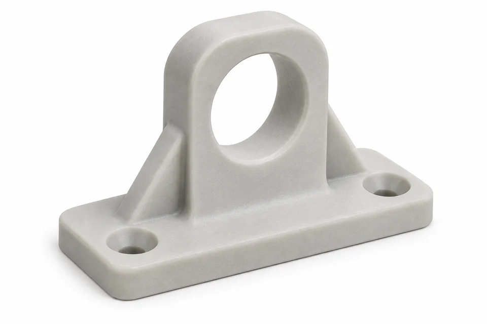
Material selection
Match the material to the job
Start with what the part must withstand. Then select the exact product, process and finish together.
- Load
- Direction, duration, impact and repeated movement
- Environment
- Heat, moisture, chemicals and exposure time
- Geometry
- Fits, thin flexures, trapped volumes and supported faces
- Delivered state
- Conditioning, cure, colour, finish and inspection
| Material | Process routes | When useful | Confirm before release |
|---|---|---|---|
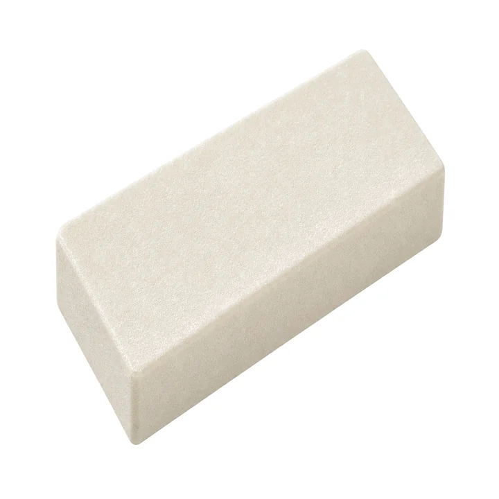 PA12Rigid nylon powder PA12Rigid nylon powder | SLS or MJF | Rigid housings, brackets and ducts. | Powder grade, build direction, moisture state and finished-part fit. |
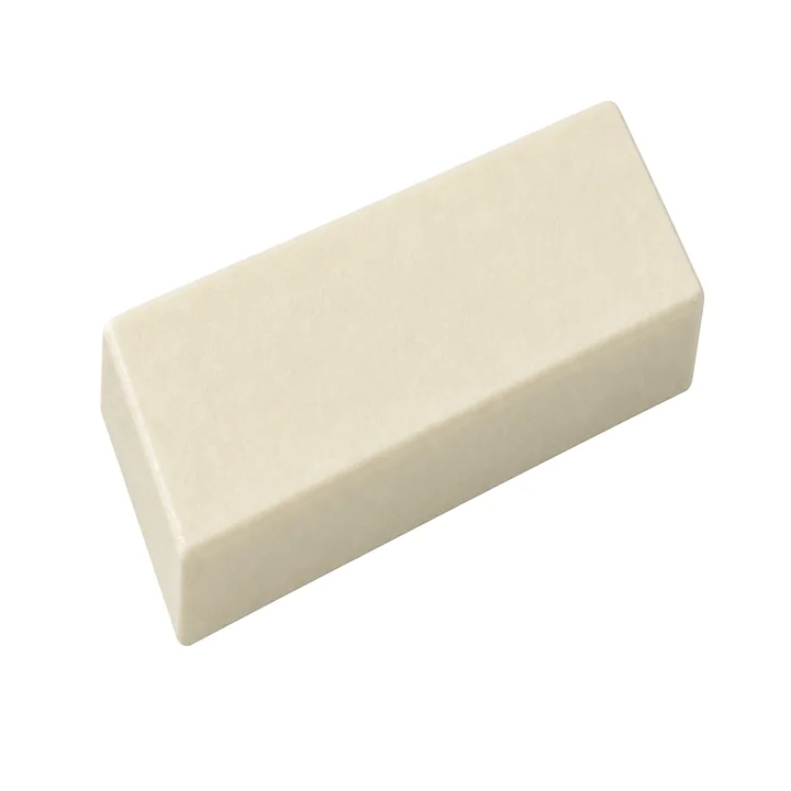 PA11Ductile nylon powder PA11Ductile nylon powder | SLS or MJF | Clips, flexures and impact-sensitive parts. | Grade-specific strain, conditioning and repeated-use performance. |
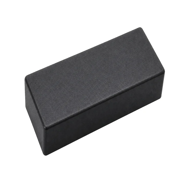 TPUThermoplastic elastomer TPUThermoplastic elastomer | SLS or MJF | Grips, bumpers and compliant interfaces. | Hardness, wall geometry, compression, tear and fatigue. |
 Engineering resinCured photopolymer Engineering resinCured photopolymer | SLA or DLP | Fine detail or a specialty resin function. | Resin, wash/cure, support marks and long-term exposure. |
| Requirement | Specify it as | Why it changes the route |
|---|---|---|
| Heat under load | Temperature, load duration and deformation limit | A melt temperature, Tg or coupon HDT is not a complete service requirement. |
| Flexible behavior | Hardness, deflection, compression, tear and cycle target | A TPU name does not predict a lattice, gasket or snap response. |
| Nylon function | PA11 or PA12 product, reinforcement and moisture state | Filled and unfilled grades trade stiffness, elongation, surface and directionality. |
| Colour | As-printed colour plus the intended finish | Mass-pigmented powder, dye, paint and clear coat are different states with different limitations. |
| Regulatory use | Required standard, test configuration and traceability | A supplier material result does not certify the finished part, assembly or application. |
Use a prototype to de-risk the production route
A representative sample should prove the feature that motivates the process choice. A show model cannot validate a loaded clip, a seal, a threaded assembly or a cosmetic production finish.
- Freeze the test question. Define the load, fit, surface, leak path or inspection result the first article must answer.
- Keep the recipe visible. Record process, material product, orientation, supports or powder refresh, finishing and conditioning with the sample.
- Measure after final finishing. Dyeing, smoothing, coating, curing and machining can each change the delivered state.
- Plan the next quantity honestly. If the design is likely to change, preserve flexibility. If it is stable, compare tooling, CNC and additive quotes against the actual specification.
Some comparisons are part-specific
SLA versus PolyJet, DMLS versus CNC, PA11 versus PA12, and printing versus urethane casting answer different engineering questions. Use the focused guide when one of those constraints drives the decision.
Surface
SLA / PolyJet
Compare support removal, visual requirements, material durability and the full post-processing workflow—not only nominal resolution.
Metal
DMLS / CNC
Use additive metal for geometry that earns its extra process steps; use CNC when tool access supports the required alloy, fit and surface.
Bridge batch
Printing / urethane casting
A master pattern, silicone tooling, finish and material behavior can make urethane casting useful for a particular low-volume polymer part.
For a materials-first decision, browse the 3D printing materials library. For quantity and cost drivers, use the 3D printing cost guide.
Frequently asked questions
Which 3D printing process is best?
There is no universal best process. Start with the part’s material, load, geometry, finish, fit, inspection and quantity. A route that is excellent for a cosmetic model can be wrong for a loaded nylon clip or a precision metal interface.
Should I choose SLS or MJF for a nylon part?
Compare the qualified powder product, geometry, surface state, finishing, orientation and order plan. Both are powder-bed polymer processes, but their material portfolios, machine workflows and finished-part evidence are not interchangeable.
Can I select a process from layer height or resolution?
No. Layer height describes one build setting, not every feature, surface, tolerance or mechanical result. Inspect the controlling feature and the intended post-processing route.
When should a printed part move to CNC or molding?
Compare routes when the design is stable and the critical specification is known. CNC often resolves precision interfaces and real-stock material needs; molding can improve repeatability and unit economics when tooling and volume are justified.
Sources and further reading
- Formlabs — FDM, SLA and SLS comparisonProcess workflow, materials and finishing are formulation- and printer-specific.
- HP — introduction to 3D printing processesOverview of additive-process categories.
- Protolabs — selecting a manufacturing processEstablished process operator guidance; supplier figures are not universal.
Specify the details that make the part work.
Upload your CAD and drawing with the material, quantity, finishing and critical dimensions. Confirm the manufacturing route before production.